From the internet came six 3views with reasonable sizes. After having them inserted into DraftSight the first check on length vs. span resulted in the following:

So far the overhead views.
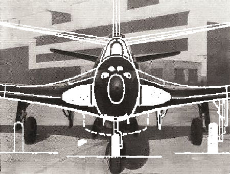
Then the side view check, using the most relevant photograph:

Like on the results of span vs. length the side view of the Aviastar 3view seemed to be the most reliable.

A reasonable wing-profile (thickness) could be derived from the same 3view-sketch and a front-view black-white photograph.
A final check, in fact the very first time as far as I remember, is the wing area.
Taking the widest available wing the area is still a 5m² short. What is to tell the truth the limit to the fuselage ?


27.3 m² vs. 25.4 m² - not too bad
At that stage, drawing the bulkheads of the nacelles and their developments, I remembered to have promised mrs. Janse of Bison Adhesives to give her liquid Kit, that should be a good equivalent for the tube Tix that was starting to clot after a longer period. The size of the brush was surprisingly large. From a modelers point of view anyway so I used an old paint-brush on the smallest (2½mm) element of the model.
Using a tweezer and magnifying-glass I managed to build a kind of cone by anointing one side of the entire cut-out element and after having waited a few minutes for the glue to penetrate molded it carefully into the intended shape.

Adding the construction lines of the plane the next 'problem' appeared in the form of the vertical stabilizer.

Copying lines of top and bottom from different 'wrong' (acc. to the proportions) 3views both sides were wider than the stabilizer from the 'correct' 3view.
What's correct ?
Since there is no bottom- or overhead photo on the internet I chose two more or less profile views of fin and rudder.

Here it is clearly visible that the stabilizer fits between the produced fin's leading edge and rudder. This reference can be used on the 3view in concern.

- The discrepancy between the trusted 3view and two 'wrong' ones;
- The side view stabilizer position and width;
- Side view profile traced in cyan from a photo with the copied and rotated portside stabilizer from sketch 1. In red the stabilizer position from sketch 2 and in cyan dash-dotted the shifted stabilizer and scaled between leading edge and rudder. In conclusion it can be stated that the 3view that was we used up to now may be proportionally correct but is not as perfect as initially presumed.

Size and position ?

close ? if you find out tell me . . .


Using Rapid Tables to convert Hex color code to R,G,B in behalf of DraftSight I got:


And what about taking a photo screen dump ?


Last but not least (insallah...) the colours.
Not easy to trace normally and so it was this time but finally the IPMSStockholm site gave the following two colours.

One should have been applied on the wings and the second on the fuselage and probably there may be a visible difference in DraftSight, or on the printed pdf, but for now I do not see so much of it.

fuselage colour wing colour
The Model Paint Conversion Cart gave the following RGB equivalents for the FS values.
FS 35042 = 2B525C or 545a4c and FS 25042 = 353F45.
These values give in Paintshop Pro and DraftSight respectively the following pictures:

Using Rapid Tables to convert Hex color code to R,G,B in behalf of DraftSight I got:

The above screendump is a jpg from a DraftSight's PDF, but when the screendumped FS picture from IPMS is picked in PantshopPro the RGB's are the same (...) but different from all the others !


which one has the correct colour ?

After some picking and comparing the above choice should do. On top the screen dump values of the IPMS pictures and just below a picked colour from the nose of the photo.
Close aren't they ?
And what happened on Christmas day ?

exactly
Yeah...exackely...Cutting out the last fuselage section I could not believe to have printed that page with the layer 'decals' off, or even frozen. What happened ?
Well, plotting sheets carrying (clipped) images to PDF using DraftSight's printer-driver is still a mess. This time no rotated or mirrored clips but none at all.

1) the (blue) dotted area concerns a to DraftSight inserted 'reference image'

2) the same image, but (the white area) clipped (off) over the blue dots

3) the PDF (screen dump) as created with the indicated (built in!) printer driver

4) the PDF (screen dump) as created with the PDF995 driver
although the file is twice as large as DraftSight's, the output is correct.
chasing errors

the first mistake was a neglected mirroring.
 next it is difficult to place a bulkhead or spar (11) without knowing its position . . .
 . . . again and again these tiny but very irritant slips of the
 mouse mind


shouldn't there be an inlet ? . . .

and last but not least (I hope) the error wasn't in the drawing but in the building
the picture exhales one of the various excitements playing a role in a modeler's life...
INTERLUDE


INTERLUDE

DraftSight's built-in printer driver yet again !
So, from now on only PDF995.
back to the errors

trial number you tell me . . .

the difference between 21/12/17 and to-day

the only way: glue the 'a' edges first and wait till they are stuck firmly

serious errors & blunders were solved on the spot; there are 26 left
this was my most difficult model and I'm happy to have finished building
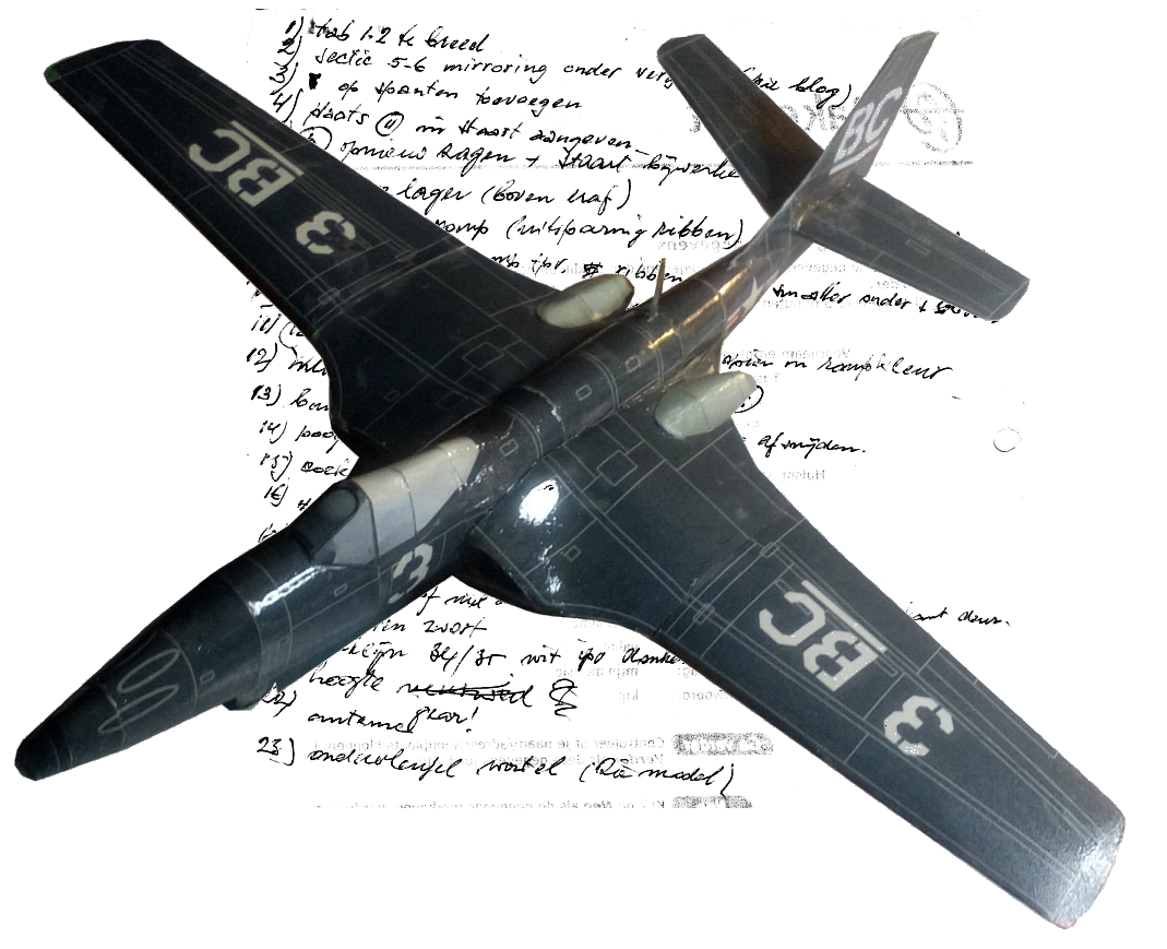
addendum error number 24

a closer look on this picture revealed a splitted door
of the gear-compartment, so 34 & 35 are wrong
Everything settled:
