And indeed it sorted out.
Step one:
Step two:
This was the only message referring to an existing Buccaneer.
Googling on these pictures I stumbled on the name Bruno VanHecke, but
who is Bruno VanHecke ?
Always interesting to see the brain waves of colleague designers.
The other Buccaneer-threads on the forum were only 'looking-fors' :
Well that's clear enough. The Buccaneer.
The internet scored an amount of twelve 3views. Never happened before..
In the Netherlands they are called (literally translated) 'sketch of measurements'.
In the fifties these small pictures were used by the Royal Dutch Association for Aviation and displayed in the section 'Vliegtuigherkenning' (airplane recognition) of their magazine Avia Vliegwereld.
Even contests were held that time.
The differences in the 3views could be due to different types.
Length and span can be accepted as 19.33m and 13.41m.
The height, just in case, 4.95m.
Since a half a meter long model does not fit in my showcase I chose a scale 1:75.
With 258mm and 179mm still a model of half a cabinet wide.
DraftSight, here we go !
Checking and scaling 3views
Now there is such a luxurous amount of 3views it's easy to put higher demands on comparing internal dimensions. E.g. three lengths in one 3view.
 | ||||||||||||||||||||||||
| taking into account that the span is always arbitrary some can be gratifying and so on
Vectorization and selection of sections
1st set-up, used on . . .
. . . sectioning (side view) of the fuselage
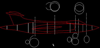
The upper figure represents two series of straight lines with minimal deviation from the actual shape. One along the top and one over the bottom line of the contour. Each breakpoint is provided with a vertical line indicating a possible position of a bulkhead.
Then (green dotted) lines are placed in the middle between two neighbouring verticals.
The connection of both ends are the solid green lines of the middle figure.
The figure below checks how far (mm) these lines are deviating from the actual body-shape.
The same procedure follows on the top-view of the fuselage where, due to its expected symmetrical shape only one contour line will have to be divided.
A connection of straight lines between the copied cross-section will cause a serious offense against the fuselage's area-rule.
Particularly the bend at the exhaust may need one extra bulkhead...
Only one was - see yellows - wishful thinking...
This should be then the 'idealised' horizontal + vertical sectioning where possible available cross sections will be inserted and adapted.
Returning to the 3views I found two identical sets of sections.
These sections are to be found on the first 3-view in this blog referring to sas.1946.com or aerofred.com which to my opinion is copied from the view below referring to britmodeller.com or rcuniverse.com.
Hoping the latter could mean that there might be an existing R/C Bucanneer I searched Youtube, but unfortunately in vain.
Talking about 'copying' I can rely on a certain capability as well and doing so I chose the most essential from a circle deviating sections below.
Hoping they will not deviate too far from the obtained hights and widths the next move is to adapt them over there an further on it's a matter of interpolation between them and with circles at the outside of the outer cross-sections.
Deviation1
|


