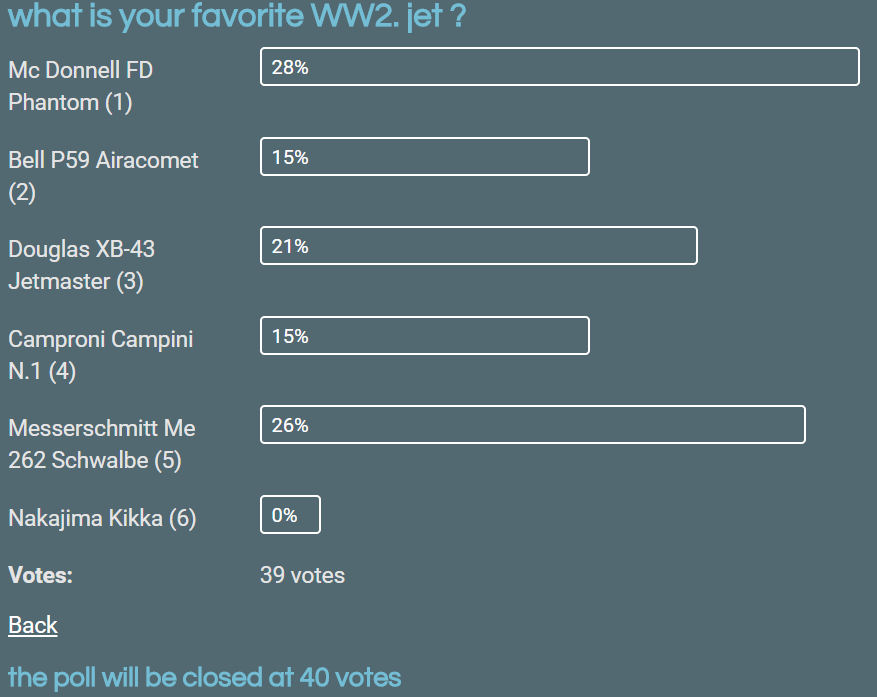
After having finished the Constellation I had to buy another glass shelf in the showcase and I thought it had been the very last model. But blood always crawls and to-day the poll on six WW2 jets (see augustus 1) came to an end.

STEP1
The search for sharp and larger 3views of the Schwalbe was quite fruitfull.

STEP2
The search for the plane's specifications very often results in contradictional data. Not seldom between linguistically different Wiki's.
Unfortunately the Messerschmitt Museum site did not provide a data-bank.

A length of 10.60 m is claimed by 5 sites where the Smithsonian War Museum gives a length of 12.1, followed by the imperial size of 39 ft 9 in = 12.16m, so not a slip of the keyboard.
A span of 12.50 is given by 4 of them and 12.60 by the other two.
The height of 3.80 (3.83) was, apart from the English Wiki with 3.50, the same.
The World War II Database specifies that the measurements of the three versions, the A-1a, B-1a and A-2a, were equal.
Hopefully the correct values of the forementioned deviations will be confirmed by
STEP3 Search for the most reliable 3view.
3.1 Check the proportion of the span, length and height.
 Using the greatest value (the span) the 3view was scaled to a scale 1 : 50.
 3.2 If the deviations are not unacceptable (here about 3mm) the body (or evt. wing) shapes have to be adjusted.
The side view of the body's traced polyline has been scaled*) -2mm in longitudinal direction, thus hardly effecting the body's height.
*) for DraftSight users only
Scaling: 1.select entity to be scaled - 2.on 'scale factor' type R - 3.on 'reference length' select the mutual point of original entity and the one of the required length - 4. on 'second point' select point N of the original - 5. on 'new length' click point N of the new shape.
3.3 Now all available 3views can be checked in relation to the one that was initially selected. It easily can be done by copying the polylines over each 3view and resize that 3view accordingly.
 The result in case of the Schwalbe is that 4 from the 9 3views were sufficiently covering each other, 2 had minor deviations, 4 were really out at different spots and one of them had Panther F-5D5 aspirations...
 After the fuselage the wings and nacelles will have to be compared and eventually checked...
 Four of the same nine 3views were wrong and only one wing was not according the majority.
If however the conflict between all available 3views would have obstructed a proper choice one has to rely on photographic material. In that case onw can recognize te shape, but measurements, even relationable, are complicated.
An example follows from an evident photographic difference in pylon-lengths of WW2 pictures versus recent shots of the Me-262 remakes.

PK from the blog Paper Kosmonaut mailed the cause of this phenomenon.
The original Jumo engines were with the length of 3.86m three times as long as the remake's General Electric CJ610 with its 1.15m.
The afterburner version could be another 15cm longer.
Determination (nacelle vs. fuselage) the actual length from photographic material one may not rely on pictures as the side views above because of perspectivic distortion.

Proportional measurements only can be done with impunity when the objects are on the same distance from the camera, in the center of the picture and the camera was in a perpendicular position towards the objects.
In order to evitate the influence of the lenses spherical aberration they should not be to far away from the center of the picture as well.
The farther away from the object, the less this influence (as well as the perspective).

As far it concerns the nacelles position and width the above pictures prove the usability of the applied 3view.
STEP 4 Determination of articulation points on the fuselage.
The beauty of planes is mainly their aerodynamic body shape.
For the draftsman of paper models however it is the major challenge.
How to simulate a smoothly curved object using the straight shapes of cones and cylinders ?
4.1 Drawing a second (cyan) polyline as a series of straight vectors along the top and bottom of the polylined side view taking care to stay as close as possible to the curved original (red) one. The same over the top view.
 To give an idea how far, or how close, the straight figure deviates from the oroginal shape the mm are displayed below.

4.2 These articulated points could be the bulkhead positions, but certainly some of them will have to be moved a few cm sideways in order to avoid a series of hardly to build very small fuselage sections.
Let's have a look.

4.3 As stipulated under 3.2 the section-lines of top- and side view have to be idealized. Their averaged position is displayed in thick red.

4.4 How far this alteration is effecting the shape of top- and side view is displayed as the two top figures below in green.

4.5 Removing one bulkhead (the third red from the right) and adding three new positions improves the division by exchageing 3 x half a millimeter and one 0.6 millimeter for two 0.4 mm.
Disadvantage is more smaller elements requiering more skillful building.
STEP 5 Bulkheads; determination of cross-sections.
If you're so lucky to find 3views or dynamic model building plans providing ready-to-use cross-sectional shapes the only remaining thing is checking them with the width and height of drawing 4.4.
If you're not then the only way is to find one typical crosssection - mostly frontal pictures and deform it proportinally along the body.
5.1 In case of the Me262 the internet is really generous.
 The cross sections imported in DraftSight are proportionally distributed over the side-view of the traced 3view, scaled in relation to the height of the model and some of them are interpolated between the available ones.
Of course the widths haves to correspond with the heights.
In this case two considerable corrections (both due to in- or extrapolation) are to be made.

STEP 6 Construction of the fuselage
6.1 Since we have made a programme in QB64 the development of the conical sections is peanuts.
6.2 The bulkheads are drawn by mirroring the cross-sections (cyan).
One wants to build them from 2mm cardboard or other stiff material, the other prefers the old-fashioned teeth.
In odwer to serve them both there are two different linetypes that speak for themselves.


Okay, it will be number 17 then, but what about this 17 ?
A span of 12.50 is given by 4 of them and 12.60 by the other two.
The height of 3.80 (3.83) was, apart from the English Wiki with 3.50, the same.
The World War II Database specifies that the measurements of the three versions, the A-1a, B-1a and A-2a, were equal.
Hopefully the correct values of the forementioned deviations will be confirmed by
STEP3 Search for the most reliable 3view.
3.1 Check the proportion of the span, length and height.


*) for DraftSight users only
Scaling: 1.select entity to be scaled - 2.on 'scale factor' type R - 3.on 'reference length' select the mutual point of original entity and the one of the required length - 4. on 'second point' select point N of the original - 5. on 'new length' click point N of the new shape.
3.3 Now all available 3views can be checked in relation to the one that was initially selected. It easily can be done by copying the polylines over each 3view and resize that 3view accordingly.


If however the conflict between all available 3views would have obstructed a proper choice one has to rely on photographic material. In that case onw can recognize te shape, but measurements, even relationable, are complicated.
An example follows from an evident photographic difference in pylon-lengths of WW2 pictures versus recent shots of the Me-262 remakes.

PK from the blog Paper Kosmonaut mailed the cause of this phenomenon.
The original Jumo engines were with the length of 3.86m three times as long as the remake's General Electric CJ610 with its 1.15m.
The afterburner version could be another 15cm longer.
Determination (nacelle vs. fuselage) the actual length from photographic material one may not rely on pictures as the side views above because of perspectivic distortion.

Proportional measurements only can be done with impunity when the objects are on the same distance from the camera, in the center of the picture and the camera was in a perpendicular position towards the objects.
In order to evitate the influence of the lenses spherical aberration they should not be to far away from the center of the picture as well.
The farther away from the object, the less this influence (as well as the perspective).

As far it concerns the nacelles position and width the above pictures prove the usability of the applied 3view.
STEP 4 Determination of articulation points on the fuselage.
The beauty of planes is mainly their aerodynamic body shape.
For the draftsman of paper models however it is the major challenge.
How to simulate a smoothly curved object using the straight shapes of cones and cylinders ?
4.1 Drawing a second (cyan) polyline as a series of straight vectors along the top and bottom of the polylined side view taking care to stay as close as possible to the curved original (red) one. The same over the top view.


4.2 These articulated points could be the bulkhead positions, but certainly some of them will have to be moved a few cm sideways in order to avoid a series of hardly to build very small fuselage sections.
Let's have a look.

4.3 As stipulated under 3.2 the section-lines of top- and side view have to be idealized. Their averaged position is displayed in thick red.

4.4 How far this alteration is effecting the shape of top- and side view is displayed as the two top figures below in green.

4.5 Removing one bulkhead (the third red from the right) and adding three new positions improves the division by exchageing 3 x half a millimeter and one 0.6 millimeter for two 0.4 mm.
Disadvantage is more smaller elements requiering more skillful building.
STEP 5 Bulkheads; determination of cross-sections.
If you're so lucky to find 3views or dynamic model building plans providing ready-to-use cross-sectional shapes the only remaining thing is checking them with the width and height of drawing 4.4.
If you're not then the only way is to find one typical crosssection - mostly frontal pictures and deform it proportinally along the body.
5.1 In case of the Me262 the internet is really generous.

Of course the widths haves to correspond with the heights.
In this case two considerable corrections (both due to in- or extrapolation) are to be made.

STEP 6 Construction of the fuselage
6.1 Since we have made a programme in QB64 the development of the conical sections is peanuts.
 |
| the Fish... |
One wants to build them from 2mm cardboard or other stiff material, the other prefers the old-fashioned teeth.
In odwer to serve them both there are two different linetypes that speak for themselves.

For the 'toothbuilders' the figures are drawn twice.
6.3 After the arrangement of bulkheads, joining-strips of the fuselage-sections and these sections themselves the drawing looks quite impressive but

the result is only two pages with the basic elements of the body.

During the development of the fuselage a minor flaw was accidentaly recovered. Perfect moment to combine a longtime planned translation and an adequate guide of the development programme. Both have found shelter with Google Drive and from there they can be approached and downloaded by any paper-colleague working with DraftSight or Autocad®.
Just click
Back to the drawing. Now the fuselage has been tackled the wings, and rear stabilizers are the only primar elements left.
Vectorizing the frontal view it was worthwile to place the largest fuselage-section, number 6, on top of it.
Like the side-view was compared with all available 3views only a few didn't fit which ment that section 6 had to be reviewed and very likey the sections at both sides as well.
 |
| collected and applied bulkhead 6 in red |
As a direct result of this failure both developments - and probably the ones next to them as well - will have to be replaced too.

Now the fuselage was ready the next rounded body, the engine could be cheched by comparing 3view and picture.

That looks perfect. The fuselage discrepancy is a matter of perspectivity.
But then...
On the search for close shots of the nacelles the bulkhead-problem was back...

A second picture endorsed the kinks at the front and rear end of the wing root.

The wing root section and adjacents had to be reviewed and re-developed.
Bit-by-bit the basics are growing...

With the basics finished it's time to choose an authentic bird.
 |
| 17 |

all 17's front and what about this one then ?
And then, just finished colouring the entire fuselage according to the only available '17-colours painting', for one reason or the other I surfed again along the net. This time asking for 'Me262 colours'. And look what happened...

And I still have the feeling that the initial combination can easily be applied.
Well, after quite some time fiddling around with various R/G/B-combination I decided to leave the texture-nightmare and now I'm ready to start the cutting.

Surprise surprise... The cutting can start yes, but the glueing is 'different cook' since my better half used and put the glue flask back into my paper-modelers' plastc tool-box. The cap-plug wasn't closed then (now it is!) and the dispenser nozzle pushed back inside the flask (pls. try it yourself....).
Whatever happened we will never know, but the flask is as hardened as the entire toolbox compartement....
Up to Gamma one of these days.

BUILDING

 |
| with the 1st nine observations |
BUILDING
Without having paid a dime for their professionally shaprd software every year again I get noticed by email when an updated version is available for download.

Except for engines, gear and the drawing the model is finished.

It's not new. The last straw breaks the camel's back...
And nearly that one of my Swallow as well.
After a proper PDF-print of the first three sheets not only the preview of page 3 was messy but the PDF likewise. But for me not a brandnew phenomenon and
probably there was an answer meanwhile on this question that I placed in the DraftSight community in june of this year.
There was !

These were the drivers he meant: PDF995, Microsoft PDF and PDF (DraftSight).

And so I used all three of them with the following results (files with their mb's).

And then came sheet number 5, called page 4. That was a mess, a real mess...
Whatever I tried, there reamained a white gap in the tail's stabilizer.
After quite some trials I returned to the community a dropped another query.
Then, at the end of my tether, I copied sheet 1, called it working sheet and shifted it over the page 4's area in the dwg. One Zoom at 1:1 scale, thr sheet locked and print (again!).
And there she was.... error free.
Happily I re-entered the communtiy and edited my last message.
PROBLEM SOLVED

Well, that's more or less the birth of my 'Schwalbe'.
It's time to leash the stuff to mankind 😇...
The stuff...


Then, when you think to have finished everything fortunately a mail comes in with the fact that page 4 is frayed...

So the printer-configuration was still worrying !

The DraftSight's A4 sheet-config meshes up the colours (clipped images...) where both other configurations, PDF995 and Microsoft Print To PDF, are indeed showing rough fat lines and heavy colours.
 |
| configs from left to right DraftSight A4, Microsoft and PDF995 |
Several trials as well as requests on the DraftSight forum did not bring a solution so I decided to send an apologize to all downloaders.
Only one possible solution could be to hatch the texture areas, maintaining the two RGB's derived in PaintshopPro.
 |
| RGB colours from PaintshopPro |

So far so good but, thinking not to have considered all hatching-possibilities within DraftSight I once again gave it another try...
Having gone through all different options, in particular the scale with hatching (not present when using multi-colour hatch...), I found only one (terrible) solution. Hope to explain it a bit as follows :

And then,when I wanted to share these exercises with colleague hobbyists, the link DraftSight on the good-old DraftSight community all of a sudden is inaccessible...
It is clear to me that painstaking work lays ahead but that's the way it is.
Once more the clipping-mess that passed by...

At that moment a light went on...It wás a matter of mirroring, however not horizontally but very probable vertical ! Another trial :
 |
| the 'normal' PDF of a clipped image PDF of a clipped and vertically mirrored image |
Well that's the solution, but who's going to tell you the cause.
Fortunately the Community was accessible again enabling me to write this update to the PDF-question.
Have been mirroring this morning over and again and refrain from reporting this mess. Thinking about the drivers outside DS not effecting the clips position I considered a re-installation of DS using a 2015 exe. While searching for it I stumbled over the following :
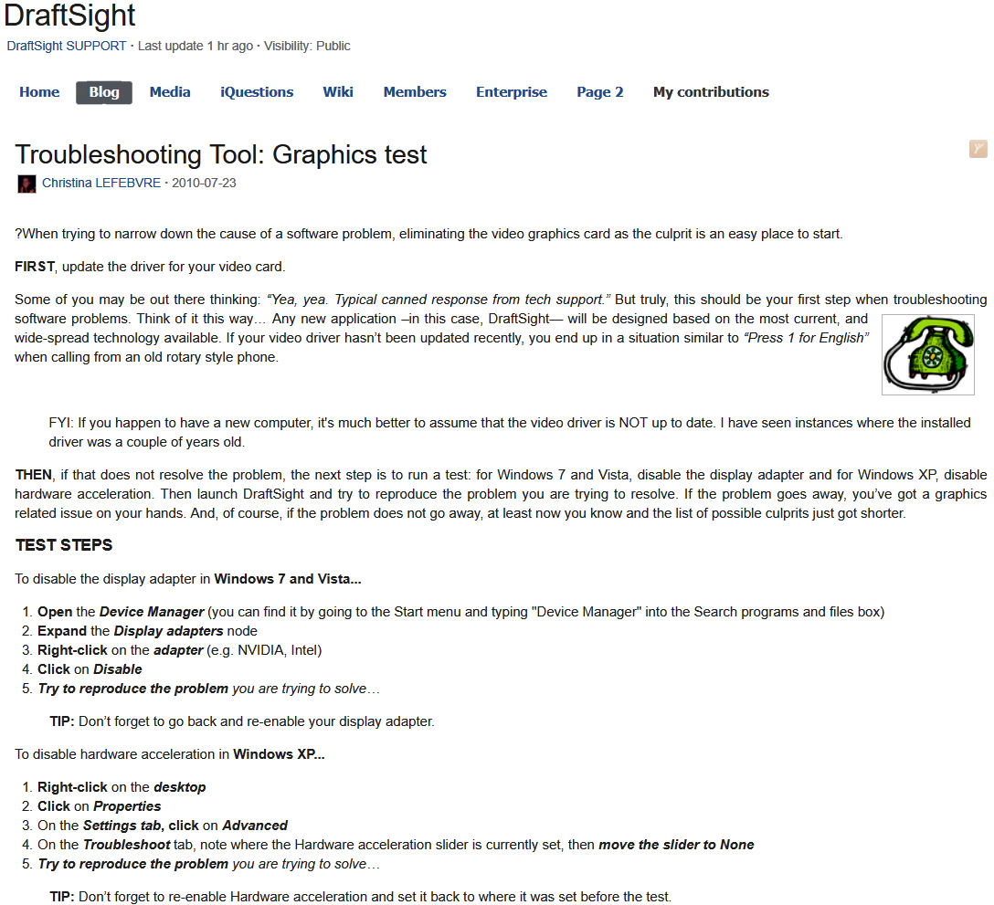
with te following result...

Well, let's clean up DraftSight.
I mean let's try to establish a so-called clean installation of a primitive version...

This is the end. The very end !
The rules and regulations above yield for every piece of software other than Windows10 so DraftSight got uninstalled the way all programs are unininstalled nowadays.
The newly installed 2015 version of DraftSight started with a failure so the latest DS update is now back on my machine.
The result of the whole exercise is this

So, as said, this is the very end. For the time being anyway. If I ever return to clipping then it will be fairly certain not in DraftSight !
And so it happened.
With 'the Voice' in mind and refraining from any kind of comment, the result: