A few weeks ago Sergio Viñals sent me his F27, the model I drew in March 2001. And again a forgotten (to correct) error in the drawing!

Building a model from a just finished drawing I use to write down every failure in this drawing. Normally scoring an amount of about thirty errors the purpose of this list is to apply these remarks in the drawing straight forward.
Here however it is evident that correction of the suspension of nacelles was dropped. A very nasty one since not so long ago PaperKosmonaut confronted me with exactly the same error (item3) on a different model of mine.
Building the Fokker in 2001 I had found the error and, according to the picture I then made, corrected it too.
 But not in the drawing, or.... I forgot to save :-(


The lengths of both curved (red) lines, one in 3D, the other in the plane, is the same.
To determine the position of the (curved) wing top one needs a series of parallel lines in te plane.
I will save you the construction of all points p but assure you the collection of supporting lines and circles, yes confusing !
Therefore I'm now on a second programme besides the development of a fuselage, the intersection of two stereometric planes. Fuselage and wing.


Easy does it - just trace the shapes and take everything for granted. The answer to this 'discrepancy' is a photographer's 'error'.
So a bit too long means a new set of developments. There we go.

The above was my last modeling convulsion.
To-day, the 30th of October 2019 I replaced my cutting-mat and opened up DraftSight again; for how long by the way ?
 Quite quick I found out the terrible consequence of a crumbling memory and alertness and asked myself "How for God's sake didn't I notice such an awful stupid folly not only having noticed my miswriting 1 : 57 instead of 1 : 75 but even went on drawing on this scale ?


This 'print' was carried out in a quicky. But the PDF-output was missing jpg-related elements (textures that were created by using imported - and 'clipimaged'- jpg's) s.a. window panes.


 and then, on Monday 27th of January,
Per consequence it is the end of our Friendship too. The 24 corrections that were outstanding never will be applied and so the drawing comes to its end as well.

Here however it is evident that correction of the suspension of nacelles was dropped. A very nasty one since not so long ago PaperKosmonaut confronted me with exactly the same error (item3) on a different model of mine.
Building the Fokker in 2001 I had found the error and, according to the picture I then made, corrected it too.

Rouhly going through the 2001 drawing I found more incorrect stuff, such as the wings center part of which the leading edge should follow the one of the entire wing and not drawn rectangularly to the fuselage axis.

Step 1 - Data
Okay then, here we go again.

https://nl.wikipedia.org/wiki/Fokker_F27
https://en.wikipedia.org/wiki/Fokker_F27_Friendship

http://www.flugzeuginfo.net/acdata_php/acdata_f27_en.php 

https://www.militaryfactory.com/aircraft/detail.asp?aircraft_id=1865

http://www.saam.org.au/wp-content/uploads/2014/12/SAAM-Profiles-FOKKER-F27-FRIENDSHIP.pdf

https://www.airliners.net/aircraft-data/fokker-f-27-fairchild-f-27-fh-227/217

https://contentzone.eurocontrol.int/aircraftperformance/details.aspx?ICAO=F27&

http://www.fokker.com/sites/default/files/media/TCDS_EASA%20A%20036_Fokker_F27_Iss_06_20160715.pdf

https://www.nmm.nl/zoeken-in-de-collectie/detail/471420/

https://www.ipms.nl/artikelen/nedmil-luchtvaart/vliegtuigen-f/vliegtuigen-f-fokker-f27
The height may vary now and then by a quarter of a meter, most of the aviationers agree.
Other figures, concerning the length, differ amazingly, but the Dutch are champion.
Their mk.100 length of 23.80m has to be 23.56m, the same length as the mk.200, of which they think it was 23.50...
Striking to see how Dutch people having monopoly on wisdom use to click the enter key without checking their nonsense.
Both length figures are wrong and I know now to have blindly accepted their values in 2001.

23800 : 57 = 417.5mm
I think to stick with the mk.100/200 as well as 1:57 so the new baby will become
29000 x 23560 mm = 508 x 413 mm, so half a centimeter shorter.
Surfing on 'Fokker F27' you'll find quite some 3views between the enormous amount of pictures.

Like with the data these sketches generally are not what the Dutch term for 3view (sketch of measurements) pretends. Going through the entire bunch one sketch proved to be smack on the actual measurements. My very first experience.

smack on
Remains to check wings, stabilizers and body widths.
As usual I hope to find appropriate photographic material.

vertical stabilizer o.k. (thx. Sébastien Gigot)
Remaining hor. stabilizer, wings and fuselage.
Taking the wing-shape for granted it is easy (in Draftsight anyway) to check the area.
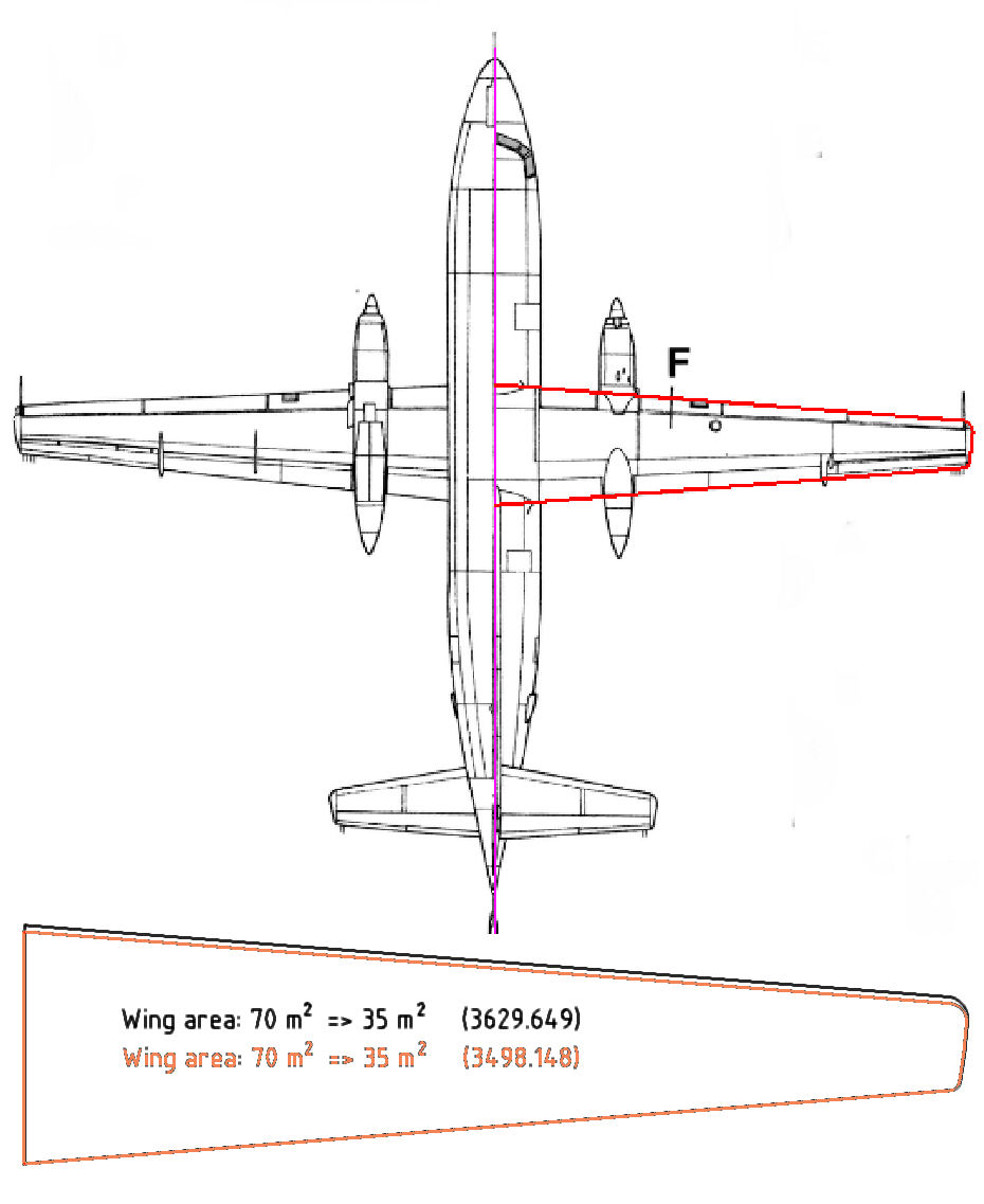
just a minor correction
Horizontal stabilizer is not expected to be easy to check. Nor shape, neither width.
The only way is a picture of a low pass-by...
And :
Thus :
hor. stabs. 👍
In behalf of the check on fuselage proportions the picture as taken by Willem Honders and published by Airliners.net was more appropriate since the lense-axis was rather perpendicular to the line of flight.

discrepancies on cockpit and vert. stabilizer
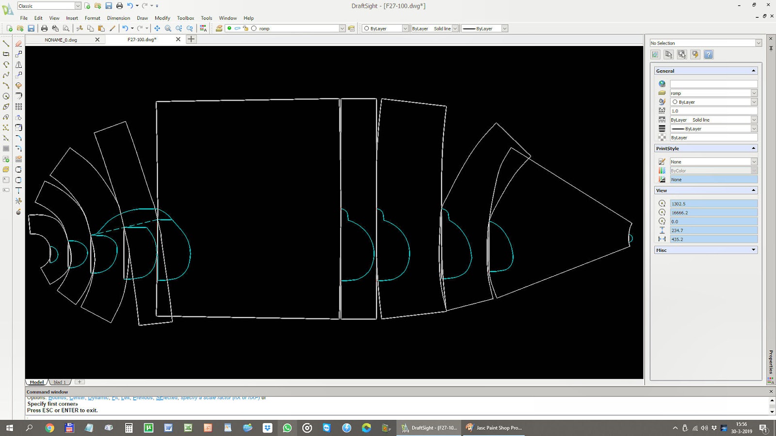
Step 2 - dividing the fuselage
To immitate a plane's streamline using only flat pieces of paper can be done by careful ironing the curves.
The use of the CAD's polyline function is a perfect basis to start looking for start- en endpoints of the curvatures.
The principle this not too complicated. The combination of top - and side views is...

The black CAD polyline is created by digitalizing (just tracing) the most reliable 3view.
The points 1, 2, 3 and so on are easily found clicking the polyline and, even easier, using the endpoint snapmode a second (red) straightlined polyline is drawn in one single action.
A third (green dashed) polyline along 1, 2, 3 and all points in between will generally do the trick. Building a Blimp or a Zeppelin you had been ready now.
Fortunately (long live the challenge) the fuselage of an aeroplane is not that symmetric.


check and adapt widths
of top- and side view
Well, now the positions of the formers has been established, what belongs to the fuselage and what to the stabilizer ?

just only integrate the top rim or the entire (blue) tail fairing ?
Step 3 - developping the fuselage
Step 4 - creating the first two pages
For two reasons the developments and formers need to be placed on seperate pages.
1) The pages, called sheets in DraftSight, are the basis for scaled PDF-prints;
2) Formers are to be printed on ordinary 60grams prinring paper and then glued on cardboard. All other elements will be printed on 160/180gram.

I set DraftSight's print configurations to PDF995 sheets instead
of its standard PDF-plot and since the drawing was already scaled
to 1:57 the sheets themselves are not scaled

Outstanding are the recess for wing-suspension, decals and texture. The first always is a nasty manual drawing-job because it concerns an intersection of two curved planes.

the width of the gap is equal to the lengths of all (red)
fuselage-arcs between the wing front- and trailing edges
From an email of one of my colleague-papercutters I understood the above picture is quite confusing so here's a second one:

The lengths of both curved (red) lines, one in 3D, the other in the plane, is the same.
To determine the position of the (curved) wing top one needs a series of parallel lines in te plane.
I will save you the construction of all points p but assure you the collection of supporting lines and circles, yes confusing !
Therefore I'm now on a second programme besides the development of a fuselage, the intersection of two stereometric planes. Fuselage and wing.
Ready !
|


Last step (5) - templates, colours, badges, roundels etc.
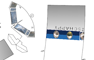
Having an enormous amount of minutes available I do not bother to reconstruct lettering. Here I found a funny 'slip of the KLM paintbrush'.
Or was it done on purpose ?

The translated text would have been 'dutch aviation company' and in correct Dutch
it has to be "maatschappij" instead of "maatschappy".
But what about the not Dutch speaking reader. Where a Dutch IJ is pronounced as an English I the 'wrongly' used Y in Dutch remains an English pronounced I.
So no worries plus an 'accidental' happy end ;-)
Most of the aircraft templates and squadron-badges a.s.o. can be found on the internet but from time to time they are as rare as the one of QAPS.
As usual however, persistence pays off.

Tripping over...
And then, all of a sudden (and very fortunate) you stumble on an odd phenomenon. What about the nacelle's shape and length...
 |
| find the differences... |
The closer to the lense, the bigger the object.
So a bit too long means a new set of developments. There we go.

The above was my last modeling convulsion.
To-day, the 30th of October 2019 I replaced my cutting-mat and opened up DraftSight again; for how long by the way ?


1 : 1 or 1 : 57
1 : 1 would have made a half a meter wide model and not fitting in my show case. But after about one hour everything came out of the wash.


But hold on.. What about the course of the horizontal stabilizer towards the fuselage (connection 8) ? The front edge of the stabilizer (9) is a sharp nod.

Having cut all girders, bulkheads etc. I saw this shot on Facebook's PaperModelers

and I still wonder what kind of material has been applied. The stuff I am using I bought with an artist shop here in Amsterdam where they call it 'woodboard' (literally translated). Straight lines can 'easily'(...) been cut with the knife, but as soon as it concerns curved edges I need to fall back on my modeller's fretsaw. With displayed consequence.
1-12-'19 to-day
After having picked up where I was, long, long ago ;-) I stumbled over quite some inaccuracies and constructiin-ideas to which sturdy 160 grams material strongly objected.
Time to re-print.
Let's first do I wanted to give a try (but forgot), change the printer settings.
O.k. ink-consuming, but...
 |
| the more intensive plot (left half) vs. a normal one |
This is what I meant to say:

and this is its consequence:

what means the 'movement' of the textures below to the section shape on top.
See you later..
January 2020 - the new year started surprisingly with an outright blunder...
...immediatly followed by an out-of-the-ordinary hick-up
January 2020 - the new year started surprisingly with an outright blunder...
 |
| oh yes, the wings.. |


nothing less to me than one huge 'pigeoned' question mark. "How come this?"


or, in Dutch, "nie begraip nie" - anyhow, to-morrow there's another day.
Indeed one other day and not just one of all others, but a fresh perspective on
the positioning of various elements using photographic information. Yes tricky !

Another 'funny' thing is the squence of the badges next to the cockpit.
Indeed one other day and not just one of all others, but a fresh perspective on
the positioning of various elements using photographic information. Yes tricky !

 |
| yes, spherical aberration |
On starboard the European mark is leading as on portside the Netherlands one
prevails.
The new (to me) way of connecting fuselage-sections - I'd like to call them 'Viñals-joints' - works smooth and accurate.
Yesterday-afternoon I found out that mrs. Micro-Soft updated her software.
The new (to me) way of connecting fuselage-sections - I'd like to call them 'Viñals-joints' - works smooth and accurate.
 |
| assuming 160gr's thickness to be 0.1 à 0.2mm I offsetted the bulkheads 0.1mm which worked out fine. |
One day she's more thorough than the other, but this time she even checked-up my available printing equipment and altered something...
What happened.
I had done the same with F27's cockpit and tried to print page 2 to PDF and obviously nothing happened. After a couple of ctr/alt/del's I suspected my PDF999-driver and decided to make use of a 'Windows-related-PDF-option' in DraftSight instead.
 |
| using PDF995 |
 |
| using the 'Standard'PDF' |
Logically one suspects the dramatically slowed down PDF995 so I decided to have a look what mrs. Micro-Soft had carried out with my printing equipment.

so I checked 'hardware/printers'
and only found the physical one
but 'once' mrs. MS gave a beautiful picture...didn't she ?

don't ask me where I found it,
but there they were...
Nothing wrong so to see, but nevertheless I uninstalled PDF995, restarted the pc and re-installed PD995 plus its Converter.
Then, re-printing page2, I opened the icon where the print stood 'waiting' and noticed a slowly growing amount of bytes...

Anyway, better slow and 'take-it-easy' ....

than no texture at all...

I had to say goodbye to CAD
 |
| shit...instead of clicking the cross... |
 |
| and they sent me the expected reaction |
1) cockpit achterkant = 4
2) tags 5-6, 7-8 en 8-9 te lang
3) vleugelneus spant 5 verwijderen
4) hoogte 4front <=24.5 mm
5) gewicht in neus
6) onderkant zijruitjes cockpit hechtlipje toevoegen
7) onderkant zijruitjes ietsje breder ivm aansl. romp - meten !
8) deel 29 nog tekenen
9) rompsectie 1-2 ontbreekt blauwe striping
10) inkeping achterlijst vleugels t.p.v. 'knobbel' 7 en rug 7-8 maken
11) hechtstrip 10 2x en 10 wijzigen in 9-10
12) pijltje bij staart (titlebloc) b bijschrijven
13) striping staart hulplijnen !
14) hokje om Fokker op de staart zichtbaar ?
15) scorepijltjes op deellijnen hechtstrook 26
16) hechtstrip staart verlengen aan achterlijst tot door de knik
17) stabilo 2x28 vernoemen 1x27 conform hechtstrips (check dubbel 27 !)
18) positoe stavilo op 10-11 veranderen (zie model)
19) stabilo's aansluiting op staart minder hol (zie model)
20) twee vleugelliggers ??
21) positie 13, 14 en 27 aangeven op de ligger
22) achterkant ribben punt afsnijden ivm hechtstrip
23) 4 schoordriehoekjes tussen ligger en 27
24) breedte vleugel controleren op de romp (zie model)
Hallo Gerard,
BeantwoordenVerwijderenIs dit niet een laser-gesneden model-basis?
Dat gaat op basis van een DWG of DXF-file uitstekend. Heb ervaring ermee...
Groetjes,
Willem
PS mooie Friendship!
Jammer Gerard, maar zijn er geen alternatieven, zoals Librecad?
BeantwoordenVerwijderenOm maar bij de 'legale' programma's te blijven...
Groetjes
Willem E.
Zonde van al je moeite!
BeantwoordenVerwijderenThx Willem voor 't meeleven. Twijfel, óf helemaal opnieuw inleven in QCad (en dan ook nog 33€ per jaar...), of in 30 dagen DraftSight trial van de F27 een deugdelijke plaat maken en dan de definitieve punt. Mja, en dan ? Alleen spelletjes wordt ook stomvervelend en de hele tafel weer volzetten met verftubes etc. etc. trekt me ook niet meer. Facebook irriteert me ook steeds meer met die toenemende lading berichten 'gesponsored' = Suikerberg's bijverdienste...
BeantwoordenVerwijderenAch Willem het leven voorbij de 80 is tobben. ;-)
Groetjes en bouw ze!
Very good first papercraft
BeantwoordenVerwijderen